
Induction Effect in Chilled Beams and Diffusers
INDUCTION EFFECT IN ACTIVE CHILLED BEAM UNITS
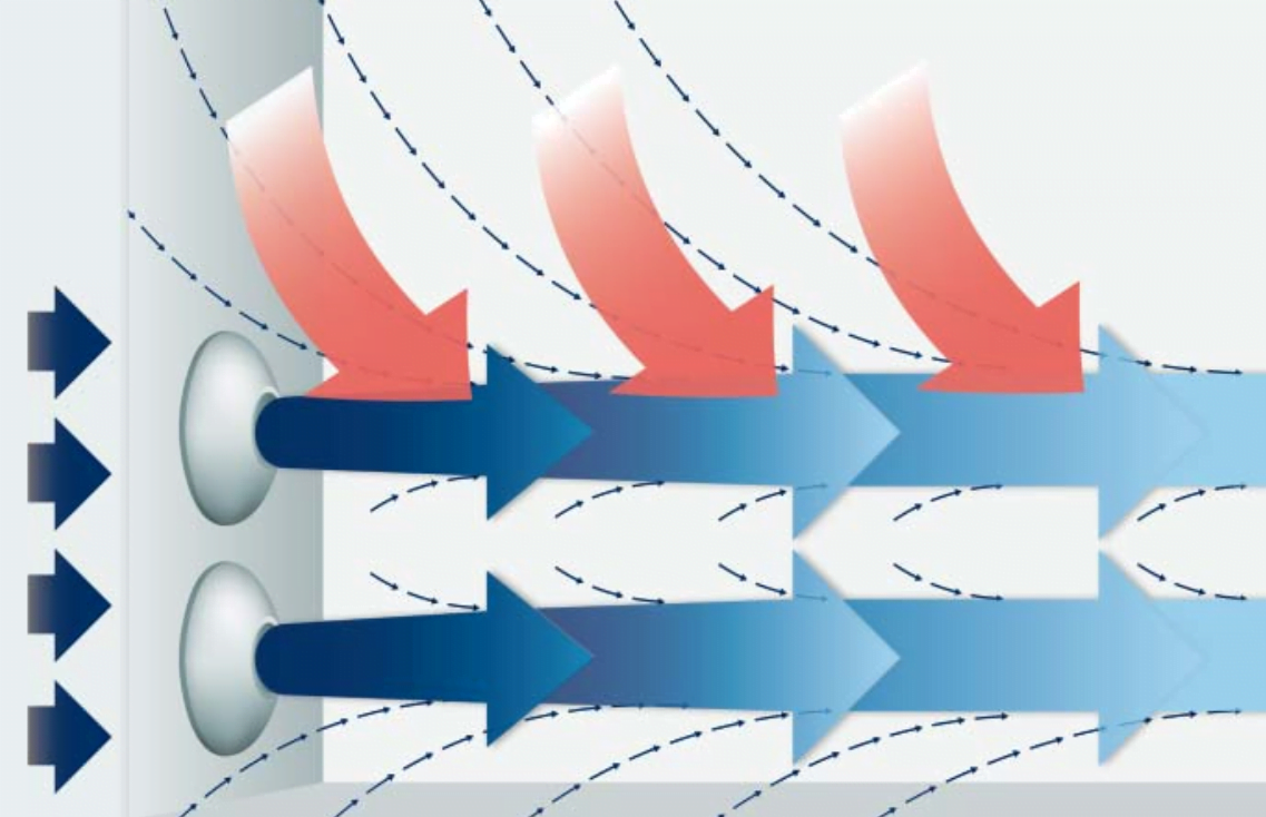
In Chilled Beams, the term “induction” is used to describe the process of primary air being blown under pressure through a nozzle, which entrains return or plenum air at the nozzle’s exit.
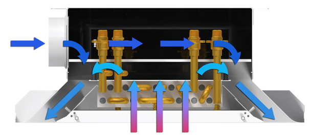
Figure 1: Induction effect in a chilled beam unit
The ratio of the amount of air entrained (induced air quantity Q) to the amount of air blown is called the induction ratio.

The induced air is drawn over a coil that heats or cools the air before it comes into contact with the air blown from the nozzle. The amount of energy transferred by the coil depends on various factors such as the induced air temperature, water supply temperature, the volume of induced air passing over the coil, and the coil surface area.
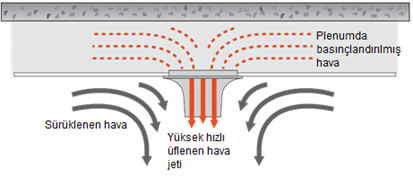
Figure 2: Process of primary air being blown under pressure from a nozzle
When designing a chilled beam system, transfer efficiency is a frequently used parameter. This is the ratio of the primary air volume to the heating or cooling energy transferred by the coil.
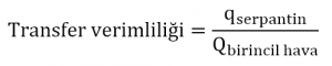
Transfer efficiency is related to the overall HVAC system efficiency. Since the air required is significantly more due to the lower amount of thermal energy it can store, transporting thermal energy with water requires less energy than transporting it with air. Several recent building designs have shown a potential gain of 10-15% in energy savings. Potential savings are higher, but are limited by the system choices made by the designer and primary air requirements. To minimize energy consumption, the primary air flow rate should not exceed the fresh air requirements.
Water is a much more efficient option for transferring energy.
When designing a building's HVAC system, knowing the induction ratio for chilled beams can be beneficial. For example, when selecting an active chilled beam for use in a patient room, ASHRAE Standard 170 recommends a minimum of six air changes, at least two of which must be fresh air. All six air changes can be fresh air, but in designs where energy efficiency is high, fresh air should be limited to a minimum of two changes. This means the designer should choose an induction ratio of 2 m³/h induced air for 1 m³/h primary air to meet the required six air changes.
For an active induction unit, the induction ratio is typically determined by calculating an energy balance across the unit. Essentially, the total energy transferred to the induced air on the water side is used to determine the induced air flow rate. The determination of the induction ratio is mostly performed using air temperature measurements. After knowing the primary air temperature, induced air temperature, and supply (mixed) air temperature, the induction ratio can be calculated. The supply air temperature depends on the number and location of primary air nozzles along the length of the supply slots and should be determined in a test environment, not on site. This will ensure accurate measurement of the supply air temperature.
INDUCTION EFFECT IN DIFFUSERS
Unlike an induction unit, the induction ratio of a ceiling diffuser is determined not by the volume of air entering an opening, but by the volume of air blown from the diffuser's opening (Figure 3). As the supply air blown from the diffuser opening moves, its velocity slows down due to the mass of air entrained and added to this air. To determine the volume of induced air, a fixed distance from the diffuser must be established, because as the distance from the diffuser increases, the volume of entrained air increases, and the induction ratio increases. Once a distance is determined, the volume of entrained air can be estimated using the supply air temperature, entrained (room) air temperature, and mixed air temperature (at the determined distance).
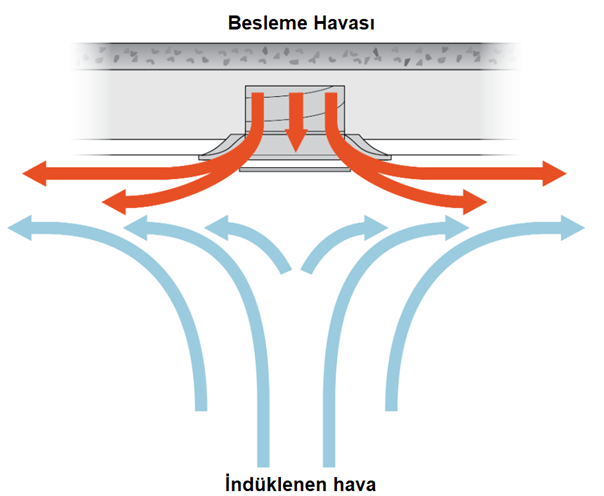
Figure 3: Air entrained along the diffuser's throw path
The mixed air temperature is not an easily determinable value, as there can be significant variations in the moving air layer. This layer is less than 1cm thick near the point of discharge, but can be thicker depending on the diffuser type. In some cases, the layer may even be separated from the ceiling. Better induction ratios can be achieved with diffusers that have regular throw patterns with high discharge velocities and are thin.
A better reference for evaluating the effectiveness of a ceiling diffuser would be the Air Diffusion Performance Index (ADPI). ADPI is a single-number rating index for a diffuser with a specified supply air flow rate, supply air temperature, and cooling load. This depends on the air velocity in the occupied zone and the draft temperature in the area.
Example of induction use in project design:
In the multi-purpose complex project example below, air distribution is provided by two different diffuser systems.
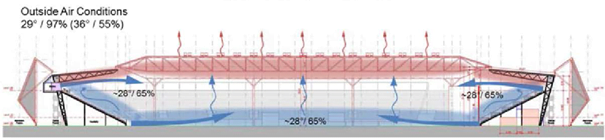
Figure 4: Application example of the induction effect of a jet nozzle diffuser
- Primary air discharged at high velocity from jet nozzle diffusers at the top of the stands towards the center of the field.
- Primary air supplied at low velocity from displacement diffusers at the bottom of the stands towards the field.
In this design; the high-velocity air discharged from the jet nozzle above the stands also entrains the ambient air from the lower sections and mixes it with the jet nozzle air. This way, it carries the primary air supplied from the lower part of the stands upwards along the seating area, ensuring conditioned fresh air circulation for the spectator section.
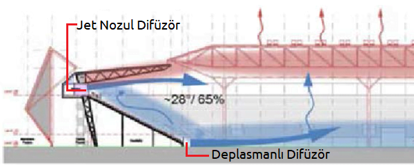
Figure 5: Application example of the induction effect of a jet nozzle diffuser-2
Sources: Price Industries Limited
Prepared by: Samet Menteş – Ender Bilgin
Induction units and High induction diffusers

Contact us for more information and project solution support:
Phone: 0216 4700070 or 0533 7323738